Introduction
The primary function of a lubricant is to separate surfaces to reduce friction. Particulates in the lubricant can disrupt the hydrodynamic or elasto-hydrodynamic (EHD) lubrication film between the metal surfaces leading to premature wear of the metal surfaces. When metal-to-metal or particle-to-metal contact exists because of a loss or break in the lubricating film, adhesive and abrasive wear occurs. This generates more wear particles that further contaminates the oil.
Sources of particulates
Solid particulate contamination can come from wear debris, dirt (silica), seals, gasket materials and scale/rust products in reservoirs and oil storage containers. Regardless of the solid contaminant type, when the size of the particulate is greater than the clearance between metal rubbing surfaces, abrasion of the metal surfaces occurs.
(Reader may refer to LUBRICATION ENEMY NO.1, MER 12/2014 by the author for more details on particulate contamination)
Typical Physical Clearance in Hydraulic Components All types of oil lubricated machinery components such as gears, vanes, casings, valves, rotors, hydraulic pumps and motors, compressors, bearings, etc are made to various standard fits and clearances. Precision rotating components such as rolling element bearings are manufactured to even closer clearances between contacting metal surfaces.
| COMPONENT | CLEARANCE μm |
| GEAR PUMP Gear Pump Side Plate Gear Housing | 0.5 – 5 0.5 – 5 0.5 – 5 |
| VANE PUMP Vane tip Vane Surface | 0.5 – 5 5 – 13 |
| PISTON PUMP Piston Bore Valve Plate cylinder | 5 – 40 1.5 – 10 |
| SERVO VALVE Control Piston Baffle Plate | 18 – 63 2.5 – 8 |
| CONTROL VALVE Control Piston Cone Valve | 2.5-23 13 – 40 |
Quantifying the number of particles in the sample
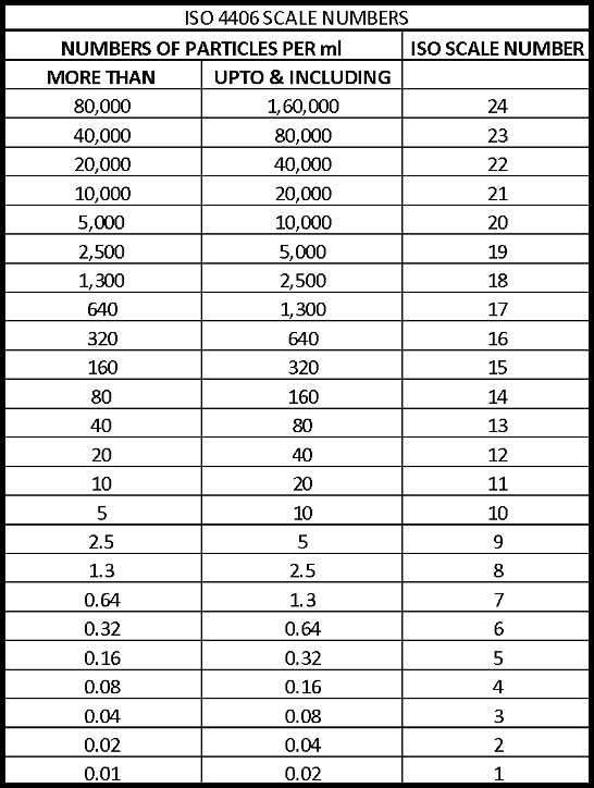
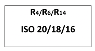
To quantify the quantity and size of solid particulate contamination in oil, ISO has developed standard ISO 4406. This standard, (see fig 2) provides the method for expressing oil cleanliness based on the solid particulate micron size and the quantity of that size particulate present in the oil. These cleanliness standards correlate to the identification of solid particulates measuring ≥ 4, ≥6 and ≥14 microns (represented as R4/R6/R14) according to the quantity of these solid particles found per ml of oil.
Acceptable limits to sizes & numbers of particulates
The clearances between rubbing surfaces for each equipment type determine the maximum particulate size that can be allowed in the oil before abrasion occurs. Besides clearances in larger components & assemblies like gears and rotors, the same lubricant may be lubricating the shaft bearings and seals that have much finer clearances. High pressure hydraulic system components, screw compressors have even tighter clearances. Rolling Element Bearing clearances are also exceptionally fine. Clearances in all the components of a system must be considered and cleanliness level that corresponds to the smallest clearance must be used when determining the oil cleanliness level required for a system (see Fig 3),
| ISO CODE NUMBERS R4/R6/R14 | TYPE OF SYSTEM | SENSITIVE COMPONENTS |
| 23/21/17 | Low Pressure Systems with large clearances | Ram Pump |
| xx/20/17 | WinGD Engine oil (Other limits for particles > 20 micron) | |
| 20/18/15 | Typical cleanliness of fresh hydraulic oil from oil manufacturer. Low pressure heavy industrial system | Flow Control Valves. Cylinders |
| 19/17/14 | Med Pressure general machinery & mobile equipment | Gear Pumps & Motors |
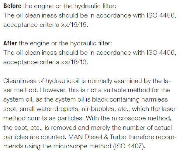
| xx/19/16 | MAN, Engine oil before engine | |
| 18/16/13 | High Quality Reliable Systems. Typical HSD cleanliness standard | High Pressure pumps & Motors. Directional & Pressure control valves |
| xx/16/13 | MAN, Engine oil after servo filter (ME Engines) | |
| 17/15/12 | Hydrostatic transmissions & sophisticated control systems | Proportional Valves |
| 16/14/11 | High-Pressure Long-Life systems and Servo valves | Industrial servo valves |
| 15/13/09 | Overly critical systems requiring high reliability that are extremely sensitive to dirt | High Performance servo valves |
Measuring the Number and Sizes of Particles in the Sample
The two commonly used techniques for measuring the number of samples in the oil sample in the lab are microscopy & laser light blockage.
Optical Microscopy (ISO 4407)
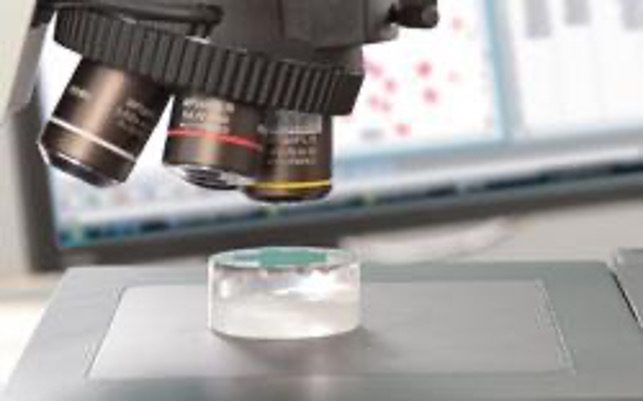
The original method for determining the level of particulate contamination in liquids used in hydraulic systems was by counting the number of particles deposited on the surface of a membrane filter using an optical microscope. Particle sizes ≥ 2 µm can be measured and counted by this method. While it is slow and expensive, it is the most accurate method of particle counting, unaffected by some of the limitations of automated methods. MAN recommends use of this method for particle count of Mn Eng. Hydraulic oil.
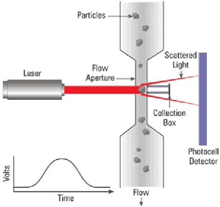
Automatic Optical Particle Counting (ISO 11500) The most widely used method for determining lubricant cleanliness is to use an automatic optical particle counter. In a laser-based APC instrument, due to the parallel nature of the laser beam, light scattering from the unimpeded laser beam is minimal, until a particle passes through the instrument. As the laser beam strikes the particle flowing with the sample through a capillary tube, light scatters and hits the photocell. There is a change in voltage across the photocell that is related to the size of the particle. Since the particles in the lube sample are not usually spherical, an algorithm generates an “equivalent spherical diameter” for the particle. Automatic particle counter does not work well with dark lubricant or one that is heavily contaminated with silt or soot or is emulsified.
Measurement of particles using an optical microscope as specified in ISO 4407 establishes the size of a particle as being equal to its longest dimension, whereas an optical particle counter derives the size of an equivalent spherical particle from its cross-sectional area, a value different in most cases from that determined with a microscope.
Expressing the PC results
The particle size/numbers measured by either by microscopy or laser method are then expressed by the ISO 4406 code number. See example below.
| ISO code number | Number of Particles per ml | |
| More than | Up to and including | |
| 22 | 20000 | 40000 |
| 21 | 10000 | 20000 |
| 20 | 5000 | 10000 |
| 19 | 2500 | 5000 |
| 18 | 1300 | 2500 |
| 17 | 640 | 1300 |
| 16 | 320 | 640 |
| 15 | 160 | 320 |
| 14 | 80 | 160 |
| 13 | 40 | 80 |
| 12 | 20 | 40 |
| 11 | 10 | 20 |
| 10 | 5 | 10 |
| 9 | 2.5 | 5 |
| 8 | 1.3 | 2.5 |
| 7 | 0.64 | 1.3 |
| Example Particle Count | |
| Size in Microns | Particle Count ≥ size, per ml |
| 4 | 6205 |
| 6 | 1854 |
| 10 | 732 |
| 14 | 387 |
| 20 | 94 |
| 50 | 27 |
| 75 | 7 |
| 100 | 1 |
A version of this article first appeared in the OCT 2021, Vol. XV; Issue. XI of Marine Engineers Review (India)
References:
- Rexroth Oil Cleanliness Booklet
- MAN Diesel & Turbo, Service Letter SL2017-644/JERA, 03/2017
- Automatic Particle Counters for Fluid Contamination Control, Practicing Oil Analyst, 02/2002
- Tribology & Lubrication (TLT) magazine, STLE (various issues)
- Machinery Lubrication magazine, Noria Corporation (various issues)
About the author:

Sanjiv Wazir is a Technical Adviser with LUKOIL Marine Lubricants. He is a mechanical engineer from IIT-Bombay. He is a marine engineer and a member of the Institute of Marine Engineers. He is a Certified Lubrication Specialist from the Society of Tribologists & Lubrication Engineers (STLE), USA and is a member of the Tribological Society of India. He has contributed to MER on marine lubrication developments in the past, and on oil contamination issues under “Lube Matters”, earlier.
He can be reached at sanjiv@lukoil.com